Cutoff Frequency Calculator
Our cutoff frequency calculator is here to help you pinpoint the cutoff frequency of different circuits. If you have trouble determining the frequency at which your circuit starts to attenuate the output signal, you've come to the right place! Join us below in a brief discussion about:
- What is a cutoff frequency?
- Cutoff frequency formula.
- Cutoff frequency of low pass filter and high pass filter.
What is a cutoff frequency?
The cutoff frequency of a circuit is the frequency from which it attenuates the output signal. Specifically, it is the frequency at which the power of the output signal is one-half of the input signal. At this frequency, the output voltage drops by a factor of .
In decibels, we measure the power gain as:
Where:
- - Output power; and
- - Input power.
Using ohm's law, we can rewrite this equation to measure voltage gain in decibels as:
Where:
- - Output Voltage; and
- - Input Voltage.
At the cutoff frequency, and . Substituting these values, we see that at the cutoff frequency:
If you need help working out the logarithm, our log calculator has your back!
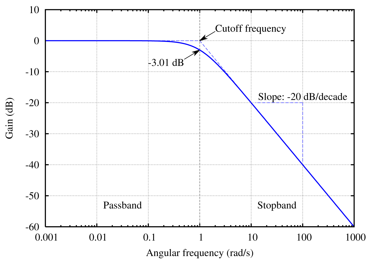
In summation, we can identify the cutoff frequency as the frequency at which:
-
The output power is one-half the input power;
-
The output voltage is 1/√2 times the input voltage; or
-
The gain in dB is -3 dB.
The cutoff frequency is also known as the corner frequency. In the following sections, we shall learn the corner frequency formulae for RC and RL circuits.
Cutoff frequency of low pass filter
A low-pass filter is a filter circuit that allows low frequencies to pass through while attenuating high frequencies. A simple RC circuit (a circuit with a resistor and a capacitor) like the one in the figure below will function as a low-pass filter.

The formula for the cutoff frequency of a low-pass filter circuit is:
Where:
- - The cutoff frequency of the RC filter circuit;
- - The resistance of the resistor; and
- - The capacitance of the capacitor.
Using this cutoff frequency formula for low-pass filter circuits, you can calculate the cutoff frequency of an RC filter circuit. Head to our low pass filter calculator to learn about these circuits in detail.
Cutoff frequency of high pass filter
Unlike a low-pass filter, a high-pass filter will attenuate low-frequency signals while allowing high frequencies to pass through unimpeded. A simple RL circuit (a circuit with a resistor and an inductor) shown below can achieve this function.
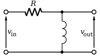
The cutoff frequency formula for an RL circuit is given by:
Where:
- - The cutoff frequency of the RL filter circuit;
- - The resistance of the resistor; and
- - The inductance of the inductor coil.
Using this corner frequency formula for high-pass filter circuits, you can calculate the cutoff frequency of an RL filter circuit.
How to use this cutoff frequency calculator
Using this cutoff frequency calculator is very easy:
-
Select the type of circuit for which you want to calculate the cutoff frequency. You can choose between the RC circuit and the RL circuit.
- RC corresponds to a simple RC low-pass filter circuit.
- RL corresponds to a simple RL high-pass filter circuit.
-
For an RC circuit, enter the values of resistance and capacitance to calculate the cutoff frequency.
-
For an RL circuit, enter the values of resistance and inductance to calculate the cutoff frequency.
Make sure you're entering the values in proper units!
