Orifice Flow Calculator
Use the orifice flow calculator to calculate the flow through an orifice. Orifices and orifices plates are common implements in fluid mechanics and hydraulics that are often used for flow metering or flow restriction.
If you'd like to learn more about this subject, you can read the accompanying text of this tool where you can learn:
-
What is orifice flow?;
-
How to derive the orifice equation; and
-
What happens with the fluid's velocity and pressure at the restriction.
What is orifice flow rate? — Flow through an orifice equation
Similar to a venturi tube and nozzle meters, an orifice plate is another type of flow meter device based on the pressure differences across it. The orifice meter consists of a circular metal plate with a concentric hole (a disk) through which the flow travels. This device is also used to control and restrict flow rate, as well as to reduce pressure. In these cases is known as a restriction plate.
In one of its typical configurations, the orifice plate is installed inside the pipe and attached to pipe ends with flanges, introducing a sudden diameter change. Let's suppose we followed the fluid traveling through this section of the pipe. We'll see that initially, it moves through a larger pipe diameter, encounters the diameter decrement, and finally goes back to the original pipe size.
This reduction in diameter, which implies a decreased cross-sectional area, translates into a rise in the fluid's velocity at the orifice and all the way through the vena contracta region, after which velocity reduces. We may see this more clearly if we recall mass conservation in the form of the continuity equation:
where:
- , and — Mass flow, cross-sectional area and velocity of the fluid before the obstruction;
- , and — Mass flow, cross-sectional area and velocity of the fluid after the obstruction; and
- — Density of the fluid.
We have a dedicated flow rate calculator, where you can learn the difference between volumetric and mass flow rates!
If we apply Bernoulli's equation at these same two points, we'll see that an increase in the velocity of the fluid, which implies a rise in its kinetic energy, means that another form of energy has to reduce. Assuming that there's no significant change in the elevation, we can omit the hydrostatic pressure terms (), and the energy conservation is expressed as:
Where and are the static pressures at the corresponding points.
This expression mathematically supports the pressure drop effect. It makes it easier to see that in order for the kinetic energy at point 2 to rise (), the pressure energy at that point must decrease ().
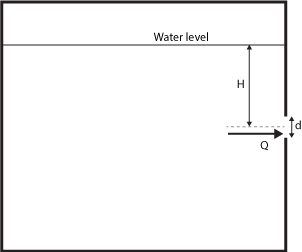
We can rewrite the above for the particular case of a free discharge setup, such as an atmospheric tank with an opening, operating in a steady flow and with constant head :
The head of liquid can be expressed as: , and because this is a free discharge case, the pressure at point 2 equals the atmospheric, thus: . Furthermore, because the velocity inside the tank is relatively small compared to the velocity at which the fluid leaves the tank, . Substituting these in the equation above:
To find the velocity at point 2:
Orifice flow refers to the flow rate through an orifice. To get this flow rate, we multiply the above by the orifice's cross-sectional area and by the discharge coefficient . This last is included to account for the hydraulic losses of the system:
where:
- — Volumetric flow rate or discharge;
- — Discharge coefficient, this one is dimensionless;
- — Cross-sectional area of the orifice;
- — Acceleration of gravity; and
- — Head of liquid above the center of the orifice.
This is the equation that the orifice flow calculator uses to calculate the flow through an orifice.
Using the orifice flow calculator
By simply entering the values of some variables, this orifice flow calculator can instantly help you determine the flow rate through an orifice plate. Let us go through how to utilize this tool step by step:
-
Begin by indicating the
Diameter of orifice (d). -
In the field below,
Area of orifice (A), the calculator will show you the area of the orifice. -
Proceed to enter the
Coefficient of discharge (Cd). -
Next, enter the mean center line in the
Center line head (H)row. -
With these numbers, the orifice flow calculator will display the corresponding flow rate in the
Discharge (Q)field.
💡 This calculator uses the gravitational acceleration of 9.81 m/s². If you'd like to adjust this value, you may do so by using the Advanced mode of this tool.