Impedance Matching Calculator
With our impedance matching calculator, you can figure out the values of inductance and capacitance required for the electronic components in an impedance matching unit. You can choose from L-match, Pi-match, or T-match topologies for matching circuits.
We've got you covered if you're unclear about impedance matching and the three standard matching networks. In the article below, let's briefly discuss the necessity of impedance matching and see how you can calculate matching networks with this impedance matching tool.
If you're interested in calculating electrical power that you must transfer through a matching unit, check out our electrical power calculator.
Necessity of impedance matching
When transmitting a signal from a source (say, a radio transmitter or a generator) to a load (like an antenna or transmission line), we desire maximum power transfer from the load. This is possible only when the load impedance is equal to the complex conjugate of the source impedance. Mathematically:
Where:
- - Load impedance; and
- - Complex conjugate of the source impedance.
In reality, the signal source and load usually have different impedances. This mismatch in impedance will result in signal reflection and loss. To ensure maximum power transfer, we use a matching unit between the load and the source, such that the impedance of the load and matching unit put together is equal to the complex conjugate of the source impedance. This practice is called impedance matching.
Three standard matching networks
There are three standard matching networks or topologies that you can choose from in this impedance matching tool:
- L-match circuit.
- Pi-match circuit.
- T-match circuit.
In addition, if the circuit must allow DC signals, it must have a low pass configuration. If the circuit must block DC signals, it must have a high pass configuration.
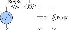
The L-match topology is the simplest matching unit. Here, the inductor and capacitor are connected in L-shape.


For calculating an L-match circuit, you need to input:
- The signal frequency;
- Resistances (Rₛ, Rₗ) and Reactances (Xₛ, Xₗ) of the source and load; and
- Whether the circuit must allow or block DC.
In return, this calculator will give you the L-matching circuit's inductance and capacitance along with the quality factor (Q).
The Pi-match topology is a matching unit where the inductors and capacitors are arranged in the shape of the Greek alphabet π.


For calculating a Pi network, you need one extra input compared to the L-matching unit calculation, which is the Quality factor (Q).
If the circuit must allow DC, the matching network calculator will determine the values of a low pass Pi-matching unit:
- Inductance (L);
- Source capacitance (Cₛ); and
- Load capacitance (Cₗ).
If the circuit must block DC, the impedance matching tool will calculate a Pi network with a high pass configuration:
- Capacitance (C);
- Source inductance (Lₛ); and
- Load inductance (Lₗ).
The T-match topology is a matching unit in which the inductors and capacitors are aligned in the shape of the English alphabet T.


For a T-match topology, the inputs required by our impedance matching calculator are the same as for calculating a Pi network. The results from the calculator will vary based on whether we choose to allow or block the DC signals.
If the circuit must allow DC, the matching network calculator will determine the values of a low pass T-matching unit:
- Capacitance (C);
- Source inductance (Lₛ); and
- Load inductance (Lₗ).
If the circuit must block DC, the impedance matching tool will calculate a T-network with a high pass configuration:
- Inductance (L);
- Source capacitance (Cₛ); and
- Load capacitance (Cₗ).
Using this impedance matching calculator
In our impedance matching calculator, you can choose to calculate for three different matching units:
- L-match topology.
- Pi-match.
- T-match.
Once you've made this choice, provide the different inputs required for each topology, including:
- The signal frequency.
- Resistances (Rₛ, Rₗ) and Reactances (Xₛ, Xₗ) of the source and load.
- Whether the circuit must allow or block DC.
- If you must allow DC, the impedance matching tool will use a low-pass configuration of the matching unit.
- If you must block DC, the matching network calculator will use a high-pass configuration of the matching unit.
- You also need to input the Quality factor (Q) when calculating a Pi network or a T network.
Based on these inputs, the impedance matching calculator will determine the inductances and capacitances required of the matching unit. You also get cool charts of the impedance and signal frequency!