High Pass Filter Calculator
With our high-pass filter calculator, you can design a filter that only lets high-frequency signals through while cutting off low-frequency ones. Our calculator allows you to create an active or a passive filter, depending on your needs.
Whether you have trouble with RC high-pass filter calculations or filter circuit configurations, you've come to the right place. In this article, we shall go through the fundamentals of high-pass filter design, including:
- What is a high-pass filter?
- Passive high-pass filter equations.
- Active high-pass filter formulae.
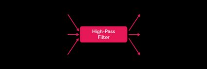
What is a high-pass filter circuit?
A high-pass filter is a circuit that allows high frequencies to pass through and blocks low frequencies. It helps remove low-frequency sounds from a track, such as the rumble of a distant train or the low hum of air conditioners. Many audio editing programs include high-pass filters, and you can also use a hardware filter to achieve the same effect. In addition, you can customize a high-pass filter by changing which frequencies are allowed to pass through.
A high-pass filter's cutoff frequency is the minimum frequency of the input signal that can pass through. The filter will attenuate all signals with a frequency lower than the cutoff frequency. This point is typically adjustable, so you can choose which frequencies are allowed to pass and which are blocked.
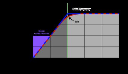
Look at the Bode plot above. We can see two lines - blue and red. The blue line drops sharply below the cutoff frequency and represents the ideal (theoretical) high-pass filter behavior. In reality, the filter cannot attenuate signals that sharply; Instead, signal strength will gradually reduce. The red line represents the behavior of such a real filter, with a smooth decline. is a point of interest at which a high-pass filter will block 50% of the signal. It is common to use this point as the cutoff frequency of a real filter.
Our dB calculator can help you understand decibels better.
Types of high-pass filters
There are two types of high-pass filters - active and passive. An active high-pass filter uses a powered amplifier to boost the frequencies allowed to pass through, while a passive high-pass filter relies on a capacitor or coil to block the unwanted frequencies. Which type of high-pass filter you choose depends on your preferences and the needs of your project.
Calculating the cutoff frequency of a high-pass filter circuit and the values of the various electrical components used in it form the crux of both active and passive high-pass filter calculations.
RC high-pass filter calculation
An RC high-pass filter is a simple passive filter consisting of a resistor and a capacitor.

A capacitor's impedance is inversely proportional to the frequency of the signal. Hence, high-frequency signals can pass through while low-frequency ones cannot.
An RC high-pass filter formula for the cutoff frequency is straightforward:
Where:
- - The cutoff frequency of RC high-pass filter circuit;
- - The resistance of the resistor arm; and
- - The capacitance of the capacitor.
For a deeper dive into RC circuits, head to our RC circuit calculator.
RL high-pass filter calculation
An RL high-pass filter is another simple passive filter that uses a resistor and an inductor.

An inductor's impedance is directly proportional to the signal frequency. Hence it will block high-frequency signals from passing through the "bridge", forcing them to go to the output. On the other hand, the low frequencies will pass through the bridge and not go to the output, thus getting blocked.
The cutoff frequency is given by the RL high-pass filter equation:
Where:
- - The cutoff frequency of RL high-pass filter circuit;
- - The resistance of the resistor arm; and
- - The inductance of the inductor.
Inverting op-amp high-pass filter
An inverting op-amp high-pass filter is an active filter circuit consisting of an operational amplifier (op-amp).

Much like in an RC filter circuit, this filter uses a capacitor to block the low-frequency signals. Additionally, the op-amp output is fed back to itself through a feedback resistor .
Inverting op-amp high-pass filter equations is not that straightforward. Its cutoff frequency depends on this feedback resistor:
The gain from the op-amp is given by:
Where:
- - Voltage gain due to op-amp;
- - Resistance of the feedback resistor;
- - Resistance of the input resistor.
The negative sign indicates that the signal has been "inverted", meaning that there is a 180° phase shift in the output signal.
Non-inverting op-amp high-pass filter
A non-inverting op-amp high-pass filter is an active filter that does not invert the input signal. An RC circuit performs the high-pass filtering, while an operational amplifier and feedback resistors provide the voltage gain.

A feedback resistor connected from the op-amp output to its positive input terminal provides the gain without introducing a phase shift. The cutoff frequency formula for this high-pass filter resembles an RC high-pass filter equation:
The voltage gain is given by:
How to use this high-pass filter calculator
You can perform active and passive high-pass filter calculations using this high-pass filter calculator:
- Select the type of high-pass filter you wish to design or calculate.
- Enter the corresponding values of the electrical components involved to find out the circuit's cut-off frequency (and gain).
Unlike a high-pass filter, a low-pass filter is a circuit that cuts off high-frequency signals while allowing low frequencies to pass through. Check out our low pass filter calculator for more.

